
100V line - Speaker Cable Lengths and Losses
Choosing the correct speaker cable for any audio installation is hugely important for both performance and reliability. With 100V high-impedance systems, you may be using hundreds of metres of cable and pushing it through some hard-to-access areas, so you want to be sure it is up to the task, both electrically and physically.
In this article: We’ll explain everything you need to know about 100V Line cable lengths and losses, including…
- Cable Lengths and Losses in 100V Line Systems
- How Cable Length Impacts 100V Line Systems
- How to Choose the Right 100V Line Speaker Cable
- 100V Line Power Loss and Cable Length
- Key Factors That Determine Maximum Cable Length for 100V Line
- 100V Line - Wiring Techniques to Mitigate Losses
- Design Considerations for 100V Line Multi-Zone Systems
High voltage, high impedance amplifiers and speakers operate in a very different way to their low impedance counterparts, and the requirements they place on speaker cable is equally different. It’s important to understand what the cable is doing as part of the circuit, and to respect that it’s capabilities can have a huge effect on performance and equipment longevity.
Let's dabble in a bit of techy spec cable theory with a nice chart or two and some useful info you likely never thought you would ever need!
Cable Lengths and Losses in 100V Line Systems
We have talked about speaker cables for installation audio systems in other guides, but here’s where things get a bit more technical. When choosing a suitable cable for your 100V line system, you need to consider the total length required and the total wattage rating of the speakers, which is then used to calculate the gauge (thickness) of the cable required.
Despite the electrical efficiency of 100V systems, they’re not magical, and your system can still suffer voltage losses and resistance issues if you don't choose the right setup.
Power Loss Over Long Speaker Cable Lengths
The main concern when running 100V line systems over long distances is voltage drop, which happens due to resistance in the copper cable. If the cable is too thin for the distance you're covering, the resistance will be high, leading to a loss in signal strength (voltage drop), which proportionally lowers the current too.
Current draw is often fairly low in these systems due to the much lower wattage requirements of the speakers, so they certainly aren't as copper-hungry as a low-impedance setup. However, they will still protest in all manner of ways if the delivery of power is made difficult by inferior cable usage.
With 100V and its impedance isolated loads, you aren't worrying so much about the potentially disastrous thermal loading issues to the amp and cable in the way you would with low-impedance wiring, but power delivery restriction to the amplifier from current draw being too high will cause the amp to lose all its dynamics (which are limited already in 100V systems), or clip into distortion.
Fortunately, you can run cables over much greater distances before this becomes a huge problem when compared to current hungry low-impedance systems, but you still need to be mindful of the cable you use if you want to ensure the best performance and avoid any equipment issues.
How Does Power Loss Affect 100V Line Performance?
Remember that voltage is the force that makes the current flow, and voltage times current (Amps) equals power (Watts) - Volts x Amps = Watts
Resistance and reactance build up in the copper cable making it harder for current to pass, which has the effect of lowering the voltage, which in turn lowers the available power. The longer the cable, the worse the effect, and the thinner the cable, the worse the effect. So, 100m of skinny cable in one length trying to power 20 speakers at 10W each is going to struggle, and there will be a significant drop in performance from the first speaker to the last.
The amplifier will do its best to compensate by working much harder, which will make it heat up, stress its components, and add in distortion to the output signal.
Voltage Drop
The voltage at the end of a long cable run may drop considerably from the input due to a build-up of resistance, leading to reduced power reaching the speakers.
For example: If a speaker is tapped at 10W but receives only 90V instead of 100V, its power output will decrease proportionally, meaning it may only have 9W or less available on the line, resulting in lower volume (the table in section 2 shows this in detail).
Uneven Speaker Volume
Due to this drop being sequential, speakers closer to the amplifier can sound louder as they receive a higher voltage, while those farther away may experience noticeable drops in volume and clarity.
This is not perceptible in most ‘normal sized’ installations as it is such a minimal difference (around 0.5dB), added to the fact that the speakers are spaced far enough apart that your ears won't notice the slight variation. However, in a large system, it can be very noticeable, especially once that loss reaches 6dB or more.
Reduced System Efficiency
The amplifier will work harder to compensate for the power loss. It will try to maintain the expected voltage at its output by producing more current, which will quickly take it out of its optimal operation levels. This extra electrical effort causes the components to produce more heat as the amp tries to produce more of everything, which will lead to greatly reduced system efficiency.
It's fairly logical behaviour when you think about it in non-electronic terms. If you match the separate parts of a system and how they are interconnected, that system can run happily at an idle speed without much effort at all. Lower the quality or capability of any individual part of that system though, and the other parts are immediately put under strain to achieve and maintain the same performance. They will try, but they will suffer for it.
How Cable Length Impacts 100V Line Systems
In a 100V system, the amplifier outputs audio signals at a higher voltage (approximately double) than you will get from a low-impedance amp, reducing the current flowing through the cable. A lower current means less power lost due to the lower resistance of the cable. However, resistance still accumulates, and the thinner the cable, the shorter the distance available before this takes a noticeable effect. If it's not managed, it can cause:
- Voltage Drop: The voltage reaching the speakers is lower than the source output, leading to reduced sound output.
- Power Loss: Some of the audio signal’s energy is lost as friction-based heat in the cable.
- Uneven Speaker Performance: Distant speakers may sound quieter or distorted compared to those closer to the amplifier on the cable chain.
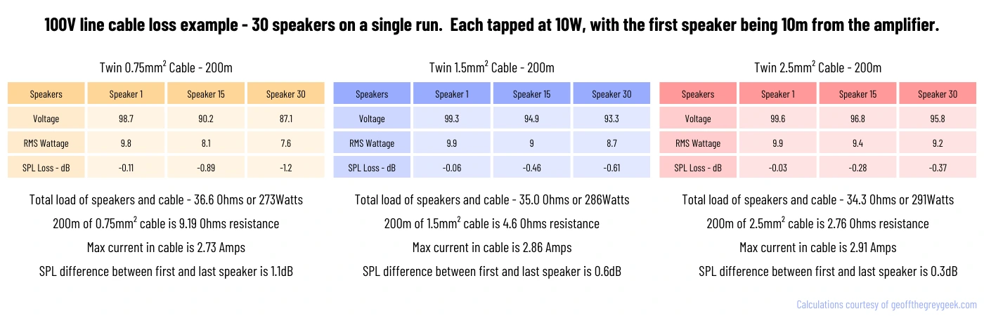
The example chart below shows the difference between three gauges of twin cable (0.75mm², 1.5mm², 2.5mm²) on the same 30-speaker, single-zone system. It has a total cable run of 200 metres with the speakers spacing divided equally along that length, and the first speaker being 10 metres away from the amplifier. The speakers are tapped at 10W.
As you will see. The losses are significant, especially with 0.75mm² cable, which is the gauge that is most often supplied in kit bundles or for ‘free’. Even the first speaker at just 10m is over half a volt down compared to the 1.5mm². At the 30th speaker, you have lost a total of 11.6V, compared to a 6V loss using the 1.5mm².
The 2.5mm² barely suffers any loss at all, just 3.8V over the 30m, which as the chart shows, translates into just a 0.3dB difference between the output of the first and last speaker, with 0.6dB using the 1.5mm², or a 1.1db gap when using the 0.75mm².
Or if it makes more sense to you as wattage, your speakers are tapped at 10W. Using the 0.75mm² cable your first speaker is seeing 9.8W, while the 30th is only seeing 7.6W. This is a progressive loss over the distance, and as the chart shows, the 15th speaker which is the ‘middle’ of the system is down to 8.1W.
It's complicated and simple at the same time. Your speaker can't utilise 10W of power if it’s only receiving 7.6W, and this lower current results in a weaker output. You then try to compensate for this volume difference by turning the amplifier up, but what you will find is that just gives you a louder discrepancy.
How to Choose the Right 100V Line Speaker Cable
Speaker cable is usually made from stranded copper. Copper has a naturally low resistance as an electrical conductor, but this resistance increases with cable length. This isn't an issue for small circuit connections or even a home stereo, but for installation audio, we can often cover large distances.
Cable Gauge - (Thickness)
For most 100V line systems, typical cable sizes range from 0.75mm² to 2.5mm² depending on the length of the run. As a rule of thumb:
For short runs (up to 50m):
0.75mm² or 1mm² cable is generally sufficient. Yes, there will be losses, but they will be minimal at these distances. For the majority of 100V line systems it simply will not be noticeable due to the low volume level they are run at for background music.
For medium runs (50m to 200m):
1.5mm² or 2.5mm² cable will be needed to reduce resistance and prevent power loss. Either of these is the ideal really for most systems. It reduces voltage and wattage losses to a minimum and will improve the performance and frequency response across a larger system.
For long runs (200m or more):
It’s often wise to go for 4mm² or even thicker cable, although this is quite rare for most installations, and using 4mm² is both expensive and awkward as it's fairly un-bendy (technical term..) when compared to normal twin speaker cable. In this situation what most installers do is to double up on 2.5mm², either with two runs or by using a 4-core cable and joining the pairs together. Either way you are doubling the copper.
Personally, i would only ever use 0.75mm² on a really small system, say 50W or less, with just a few speakers. A small restaurant area for example with ceiling speakers or small wall speakers. Anything over that requirement and i would automatically have 1.5mm² as my minimum cable size, but that’s down to the individual installer or the customer in the end.
Once you get above 120W, or over 50m on a run, you should really be using 1.5mm² or even 2.5mm² to give you some redundancy. The cost difference is so minimal that it just makes no sense to cheap out on cable, as it plays such a fundamental part in the system's performance.
What about the cable AWG rating?
Being a UK based company we generally stick to the standard metric wire measurement system of mm² which represents a cross-sectional area (CSA) of the conductor, as this is how cable is sold here.
- AWG stands for American Wire Gauge and differs as it is an imperial measurement, and measures the diameter of the conductor surface.
- Most cable will actually provide you with both ratings, though you must keep in mind that calculations and measurements given in any of our charts will have been done using the metric format.
- You must also be aware of the metric to imperial differences when looking at diagrams and tables online, as many cable length tables have been copied and pasted dozens of times from old articles, and most were originally written in AWG and Feet/Inches. Ive seen known imperial tables and charts being simply retitled with metres and mm², and that is completely wrong.
Why not just always use thick cables?
You might be tempted to just use thick cables (e.g., 4.0 mm² or 6.0 mm²) everywhere just to be safe, but this just isn’t necessary or cost-effective.
Thicker cables are:
- Significantly more expensive, and once over 2.5mm² will be single core only.
- Harder to work with—especially in installations where cables need to be pulled through tight spaces.
- Harder to terminate - many speakers and amplifiers won't even accept cables over 2.5mm², especially those with Euroblock connections.
- Serious overkill for short cable runs or the average 100V low-wattage installation. The voltage, current, and losses involved simply don't require a cable of that size.
In most cases, you’ll only need thicker cables for the main cable run over long distances. If you’re just connecting a few speakers in a small area, thinner cables (0.75 -1.5 mm²) will do the job perfectly fine.
You can however mix the cables on a larger system, and it's often not mentioned. This is perfectly fine, and you could run say 2.5mm² or even 4.0mm² for your main runs, fed through junction boxes. You can then use 0.75mm² or 1mm² tail feeds from these junctions to the speakers, making wiring to them much easier.
As with any electrical installation, logic and common sense are your friends, and pre-planning any sound system will ensure you face minimal issues and achieve the optimum level of performance from the equipment.
Choosing the Right Speaker Cable Type
In addition to the thickness (gauge), you also want to consider the environment. Indoor installations are straightforward, but for outdoor systems, you will need to consider some form of UV-resistant, weatherproof cable, which will come at an extra cost over standard speaker flex.
These specialist cables can have additional insulation to protect against moisture, temperature extremes, and physical damage. Or of course, you can just use cable conduit and normal speaker cable.
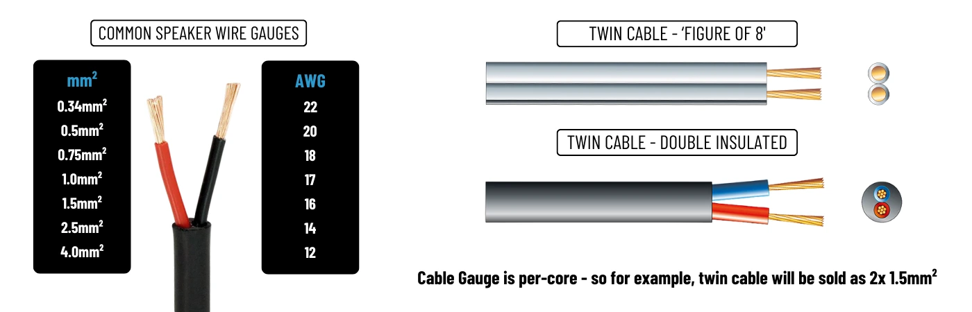
For most installations, we usually recommend a double-insulated 2-core cable over the lower-cost twin (figure 8) type. There is nothing wrong with standard twin for indoor installations, just that the additional outer sheathing of double insulated allows for much-needed extra protection from snags when doing ceiling pull-throughs and floor-to-floor runs.
The image below shows the standard cable sizes with their CSA in mm² and AWG equivalent ratings for easy reference. It also shows the difference visually between a standard ‘twin’ speaker cable and a heavier ‘double insulated’ type.
100V Line Power Loss and Cable Length
Speaker cable size selection is all about the calculated power loss in the system that the designer/installer is happy to accept, as every speaker cable conductor has a measurable resistance to current flow.
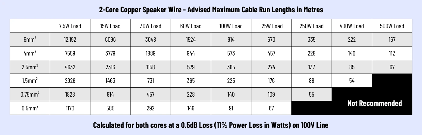
For commercial paging or background music systems, a good rule for optimum quality is that speaker cable gauge be chosen so that it offers a maximum of 0.5dB sound pressure loss across the entire system. Our first chart below shows just that, covering all the cable sizes, and system power right up to 500W, which is extremely large for a 100V system.
It can be used as a guide for the maximum cable distance from the amplifier that a speaker can be placed for an approximate maximum 0.5dB loss in SPL (roughly 11% power loss in Watts) when using a particular cable gauge with a given speaker power loading, set by the speaker's Wattage tapping.
It covers all of the popular cable sizes, and the most common amplifier power ratings you will find in the 100V line category.
The table gives the length of a standard 2-core twin copper speaker cable, which means that the resistance in the sending conductor and the return conductor have both been taken into account. The table values are calculated for the entire load to be at the maximum distance, (so for example, one big 125W speaker at the end of a cable), so for a chain of speakers you would simply add up the total power load of the speakers you will be wiring on that line, and make sure that the total length of cable is not longer than the maximum length provided in the table.
The following table shows you the maximum lengths in metres for twin (2-core) speaker cable when used for 100V line audio, calculated at 11% power (0.5dB) loss.
For comparison, we also include a second chart showing the most commonly used loads and cable sizes, but calculated at a higher loss of 1dB (20% power loss in Watts). We did this for context, as all the sites and charts I've encountered on the subject are often just presenting a single chart or table ‘as is’, with no details of calculated losses or their dB effect. Websites all tend to just give these charts as a definitive answer, yet many are calculated at 30% loss or even higher if you do the maths. It comes from the ‘what's the cheapest nastiest cable i can get away with using’ school of thought, but they give you that information as fact.
While a system will still work at those higher losses, you will be sacrificing sound quality and dynamics significantly, which you really don't want to do in any 100V installation as they are already constricted due to the way the system operates.
The following tables show you the maximum lengths in metres for twin (2-core) speaker cable when used for 100V line audio, calculated at 20% power (1dB) loss.
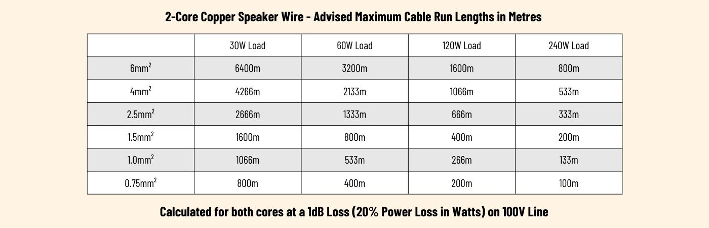
Singling out an example between the two tables here, we will look at the standard cheap cable many systems use, which is 0.75mm². As its twin core speaker cable, it's actually 2x 0.75mm², and as mentioned, the tables account for this in their results.
- 11% (0.5dB) loss on 2x 0.75mm² cable at 60W Load = 228m maximum cable length
- 20% (1db) loss on 2x 0.75mm² cable at 60W Load = 400m maximum cable length
Table 1:
Table 2:
You will see, the acceptance of an additional 0.5dB loss in performance almost doubles the cable length you can use, and this may well be perfectly acceptable for your particular installation or budgetary constraints. Background music systems are not Hi-Fi, so a lowering of system performance may not even be a perceivable thing, depending on the system usage.
We tend to promote the more cautious side of things as we look at these systems as electrical circuit components rather than audio devices, and the use of heavier cables on longer runs simply makes the system run more efficiently, will provide better performance, and will ensure equipment longevity.
Read More...
Key Factors That Determine Maximum Cable Length for 100V Line
Cable Resistance
The resistance of copper cable increases with length and is inversely proportional to its thickness. Thicker cables (lower resistance) allow for longer runs. Speaker cable resistance will always be stated in the manufacturer's specifications. However, you may be supplied with a non-branded roll of cable for your installation, so you would need to perform some calculations to determine the resistance.
Total Speaker Wattage
- Higher total wattage loading on the line increases the current draw, leading to greater power loss over distance from resistive and thermal factors.
- Higher current means greater losses, so shorter or thicker cable runs are needed for higher loads to reduce the effect.
Using Ohms Law, we can calculate the current draw from the speaker loading when connected to a 100V line amplifier.
Power (P) Voltage (V) Current (I) Resistance (R)
Current = Power (Watts) divided by Voltage (I = P/V)
For example:
- A 50W load on a 100V line = 50/100 = 0.5A current draw
- A 200W load on a 100V line = 200/100 = 2A current draw
With 100V systems, the load is spread over however many speakers you are installing, and the power level you are setting each of their tappings at. Ten speakers at 10W each is 100W of load to the amplifier, and so is one hundred speakers set at 1W. The amp doesn't care what you do with the power it has available as long as you don't ask for more than it can produce.
50 speakers, 150 speakers, it doesn't matter with 100V. All that matters is that your amplifier has enough power available and that your speaker cable is electrically capable of passing that power as unimpeded as possible.
Voltage Drop Tolerance
A 10% drop in voltage (from 100V to 90V) is usually considered as acceptable for background music or paging systems.
For critical audio applications like emergency systems, voltage drop should be kept below 5%, requiring shorter runs or thicker cables.
You should be aware of this as an installer, especially as many cable charts found online are calculated for much larger losses (I've seen as high as 30%), which is terrible.
We cover 10% and 5% tolerances in the tables in section 4. (Ours is 11% actually because it's calculated by dB loss which is a more accurate method for audio).
Speaker Distribution
If speakers are clustered near the end of the cable, the voltage drop will be concentrated, resulting in uneven performance.
Uniformly spaced speakers help minimise the impact of voltage drop. This is also the case for using multiple wiring runs to groups of speakers rather than one singular cable run.
This is because the voltage loss on 100V is sequential, and most charts and diagrams online that discuss the subject only ever reference a single load on a line (including our charts above). This is because, for most situations, that method is perfectly fine for calculating the current draw as we just saw, because the load is a set parameter. One 50W speaker is the same loading as five 10W speakers, so it makes no difference. It gives you a good enough idea of the potential losses, allowing you to adjust your cable gauge choice to suit the distances required.
However, for truly accurate voltage drop on a multi-speaker run, it's not as simple. Each speaker has a transformer to which your wiring is connected through, and each one introduces its own loss. So doing calculations for loss with a singular load will be incorrect.
You would need to calculate the voltage loss to the first speaker, and from that figure to the second and so on. It is quite complicated, and though it can be done manually, you would normally use a pre-programmed calculator which can be found online.
I've mentioned it purely to be thorough, but it is rarely necessary to go into that level of calculation with the distances and speaker numbers involved with the average 100V system.
100V Line - Wiring Techniques to Mitigate Losses
Apart from simply using thicker cables, there are a few other strategies you can employ to ensure minimal losses and optimal performance in a larger system:
Voltage Drop Tolerance
For large installations, where speaker cable lengths can stretch into hundreds of metres, multiple wiring runs can be a lifesaver, especially for systems running from a ‘single-zone’ amplifier. Instead of wiring all the speakers in a single daisy-chain configuration and requiring some monstrous-sized cable to cope, you can split the system into multiple shorter cable runs by using distribution boxes or breakout junctions.
This reduces the resistance in each segment and prevents excessive voltage drop across any single cable run, and allows smaller gauge cable to be used as each run supports fewer speakers at a shorter distance. They are all still in parallel, connected across the Com and 100V terminals, so the amp doesn't care.
For example:
As mentioned in section 3, you could run a single, thicker trunk line pair (e.g., 4mm² or double up 2.5mm²) to a junction box closer to the speakers.
From there, run shorter, thinner cable tails (e.g., 1.5mm²) to individual speakers or speaker groups. It's similar to how lighting circuits are wired, with rooms or groups of lights being fed via a ‘spur’ from the main ring circuit.
This hybrid approach balances cost, ease of installation, and performance, especially in larger venues like stadiums, factories, or shopping centres. More importantly, by wiring in spurs that way you have the benefit of an uninterrupted power line across the entire system, which means faulty speakers or damaged cables in an area will only disable that spur.
Having separate cable groups is the standard method when using a multi-zone output amplifier, but for single output amplifiers, most installers seem to only follow the basic, single cable method. While it works, and there is nothing wrong with it technically, it isn't the most efficient way, and opens you up to issues.
As long as everything is kept in parallel, you can run your cables however you like, creating zones (non-selectable) with your wiring to keep runs shorter. The amplifier doesn't care, as long as you keep within its rated output with everything that's connected.
You can take a look at a few different methods in our guide - How to wire 100V Line Speakers
Design Considerations for 100V Line Multi-Zone Systems
Many 100V line systems are installed in multi-zone setups, where each zone may have different audio requirements (e.g., separate volume controls or unique sources). Designing such systems introduces a few additional considerations:
Zone Attenuators
Adding zone attenuators (volume controls) to each area gives you the flexibility to adjust the volume locally without altering the entire system. These are passive devices that maintain the 100V signal but allow volume adjustments on a zone-by-zone basis.
When selecting zone attenuators, ensure they are rated for the total wattage of the speakers in the zone to avoid any odd behaviour.
You can read more about volume attenuators and how they function here - 100V Line Volume Attenuators
Amplifier Channel Distribution
If your system spans multiple zones, it’s often better to use amplifiers with multiple channels or dedicate one amplifier per zone. This avoids a single amp being overburdened and provides better control over individual areas. It also allows different zones to run with independent cable gauges, tap settings, and wattages.
It is important to decide early on the level of audio control you will need, as this will dictate the type of amplifier you require. For most background audio systems or announcement systems, a single-channel amplifier will do the job and allow you to play music or talk to the entire installation while keeping things really simple.
A multi-channel amplifier does the same but gives you the ability to control volume levels to each output channel or zone and make announcements to specific zones or the whole system. They still only playback audio from a single source, so you will have the same music in every zone.
A matrix amplifier basically adds an audio mixer to the front of a multi-channel amp, which provides you with independent inputs and selectable outputs. So you can have Bluetooth in your local zone, and radio, CD, or stored audio files being output to the other zones. These systems will usually feature a master override facility so that emergency announcements reach all zones at full volume, regardless of any settings that may be on the amps channels or local zone attenuators.
Slave Amplifiers
Now this may sound stupidly obvious, but many people unfamiliar with 100V audio don't consider it as they think of the system as they would a Hi-Fi, with one amplifier running the show.
Slave amplifiers are specifically designed to add extra power and additional speaker connection points to a system. They dont have preamp or zone controls (the front panels are often blank other than perhaps a master volume) and only require a line signal from the main amplifier to mirror its output. For a really large installation that covers several floors or even buildings (a school for example), you can have your main system amplifier in a central location, and run line-level signal feeds to the slave amps in those additional areas, which then feed the speakers in that zone. This is far better than running what may be 1000s of metres of speaker cable between buildings, all back to a single amp.
This can also be done with standard 100V amplifiers linked to each other, though we never recommend it for an inclusive system. The difference is that you will have a full set of controls in each area, which can be a problem, as the line signal between amps is purely audio, meaning the main amplifier cannot alter or override any setting made locally to the additional amp. So if there's an emergency announcement for instance, and the volume has been lowered on the second amplifier, you are out of luck.
Audio Over IP
This is the next step up from the slave amplification solution, and it’s a big step, avoiding all the issues we just mentioned when using multiple standard 100V amps.
AIP systems mix the world of audio with your digital network, using Ethernet cables to carry your audio signals as data between buildings. This opens you up to features such as remote switching and multi-zone control in a way that isn't easily done with a traditional 100V system without the use of relays and custom wiring.
You can have a master player and local amplifiers, or you could have players and amps in each zone if needed. They can all play the same audio feed, or playback separate music in each zone, and additions such as paging microphones can access the entire system or be software-locked to behave like an intercom.
Being software-based, these systems give you complete control of input and output distribution without requiring your amp to have hundreds of physical buttons and terminals.
The simple Ethernet connection format between devices allows for easy attaching of in-wall volume attenuators, and if you go for a full AIP installation, the speakers will also use an Ethernet cable instead of a speaker cable from the amplifier. This completely removes any voltage loss issues, and adds in the ability to address, mute, or disable individual speakers from the software.
Final Thoughts
So what have we learned? Don't cheap out on cable!!
If you're a regular to the guides, you will know I've said it before, but speaker cable is power cable, and must always be thought of this way. As crazy as some people will find it, there is no music in these cables, just voltage and variable frequency AC, and the cable's job is to get that from point A to point B in the best condition it can.
Always factor in speaker wattage (load), and physical cable distance. This is true of any audio system of course, but for 100V Line it's essential to ensure the system operates as intended.
Choose cables that are rated for the environment they’ll be used in (indoor/outdoor). When in doubt, go a little thicker on the cable to future-proof the system.
Probably the most important factor of any installation, regardless of scale, is to plan the system. You must plan properly in order to get the results you want. We have focussed on cable here, but with professional audio installation you have many other considerations that melt into the pot. Room size, ceiling heights, mounting positions, cable access, mains power access etc, and that’s just for a standard sound system in a single building.
In summary, 100V line systems are the go-to solution for large-scale audio installations. Their high-voltage, low-current nature means you can run long cable lengths with multiple speakers without worrying about excessive power loss or needing chunky cables. However, to keep your system sounding sharp, you’ll want to carefully calculate your cable lengths and choose an appropriate cable gauge to minimise voltage drop.