
How to Wire Speakers in Parallel or Series
Wiring speakers can seem daunting, especially when it's more than the standard set of two needed for stereo, but with a little knowledge, you'll have your sound system up and running in no time. Catering to the impatient amongst you, we will jump straight into the wiring layouts first (with some essential theory bits) and cover the three common methods for connecting multiple speakers to an amplifier: Parallel, Series, and Series/Parallel wiring.
Following that, we will go into a bit more detail on the important factors that are essential knowledge for speaker and amplifier wiring such as impedance, polarity, and the various connection types you can expect to encounter.
The wiring methods depicted are all suitable for two or more speakers, and our examples are shown with 4 speakers as it’s a popular setup, but can be easily adapted to suit more or fewer speakers. For simplicity, the diagrams all terminate to a single set of positive and negative connections (representing a mono amplifier output), so for a stereo amplifier the wiring would be repeated for each channel.
The cable termination method you use at each end will vary depending on whether you use component speaker drivers or finished speaker cabinets. We discuss the various connection options you may find a little later on.
Though essential for multiple speaker wiring, we won't get into impedance until later, and we have other articles covering that subject in far more depth. We set these diagrams out purely as a cable wiring reference for what to connect to where, putting the necessary calculations and theory aside. This is why the diagrams have no impedance markings.
Before connecting speakers to an amplifier, ensure you understand impedance and how using parallel or series wiring affects it.
WIRING SPEAKERS IN PARALLEL
Parallel wiring is ideal if you want all your speakers to share the same current and maintain a high output. This is the most common wiring method for both PA speakers and home Hi-Fi speakers and is likely the one you will need from the three methods. It’s also the most logical, with straightforward connections.
Understand the Concept
In parallel wiring, all positive (+/red) terminals of the speakers are connected to the amplifier’s positive (+/red) terminal, and all negatives (-/black) to the amplifier’s negative (-/black) terminal.
This configuration has the effect of lowering the overall resistance/impedance loading to the amplifier (we will look at this later), which can provide more power to the speakers, but your amplifier may struggle with the increase in required current and its associated heat production.
Connect the Wires
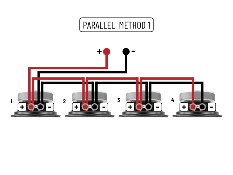
Parallel Method 1 (see image)
- From the amplifier's positive (+/red) output, take your cable and connect it to the positive terminal of Speaker 1.
- From the positive (+/red) of Speaker 1 (where you just connected to the amp), you will loop a second cable to the positive (+/red) terminal of Speaker 2, and repeat this process to the positive (+/red) of Speakers 3 and 4.
- Do exactly the same for the negative (-/black) terminals, connecting the amplifier's negative (-/black) output to the negative (-/black) terminal of Speaker 1, and looping to the negative (-/black) terminals of the other 3 speakers.
- The loops mean you will have two cables to each speaker terminal apart from the last speaker one on the line (Speaker 4 in our case), which will only have single wire connections.
As already mentioned, the method of cable termination you use at each end will vary depending on if you using component speaker drivers or finished speaker cabinets. Some cabinets have dual inputs, some have looped output sockets, and some aren't quite so user-friendly. We look at connections in section 4.
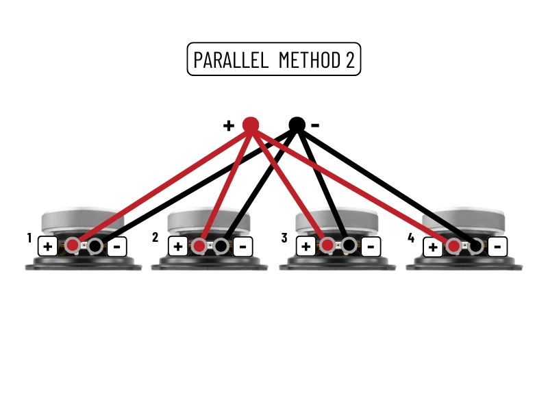
Parallel Method 2 (see image)
- From the amplifier’s positive (+/red) output, you take cables to the positive (+/red) terminals of all 4 speakers.
- Do exactly the same for the negative terminals, connecting the amplifier's negative (-/black) output to the negative (-/black) terminals of all 4 speakers.
It looks completely different but electrically is doing the exact same thing as Method 1. It's a personal preference to use either method, though it can also often be decided for you depending on the connections available on your equipment. For example, a low-cost passive PA speaker cabinet may only have a 6.35mm jack input, which makes looping between speakers a pain unless you start modifying jack cables. So Method 2 wiring would be the easier option as you can group all connections at the amplifier.
If you end up with too many wires for the amp terminals to accommodate, you can simply use some terminal strip or other cable connector to group all positives and all negatives, then take single cables from that to the amplifier’s output.
Pros:
- More output volume and better dynamics.
- Ideal for most home and live setups.
- The simple wiring helps avoid mistakes, especially when using red and black coloured speaker cable.
- The lower impedance range gets the most from the amplifier.
Cons:
- The total impedance drop will increase the loading to the amplifier, causing it to produce more current which leads to excess heat and component stress. You must do the maths first.
WIRING SPEAKERS IN SERIES
Series wiring is good when you want to increase the total impedance, or if your amplifier struggles with low-impedance loads. It has its place but is not the ideal method of wiring 4 or more speakers. It’s generally only considered over parallel when you have very low-impedance speakers or an amplifier of low power.
Understand the Concept
In series wiring, the positive (+/red) terminal of the amplifier is fed to the positive (+/red) terminal of the first speaker and then loops in and out of the additional speakers from negative to positive, until you get to the final speaker in the chain, where the negative (-/black) terminal is run to the negative (-/black) of the amplifier.
This has the effect of increasing the total resistance and impedance, which, technically speaking, is electrically safer for an amplifier’s components but will reduce the overall power output available due to the lower current being produced.
Connect the Wires
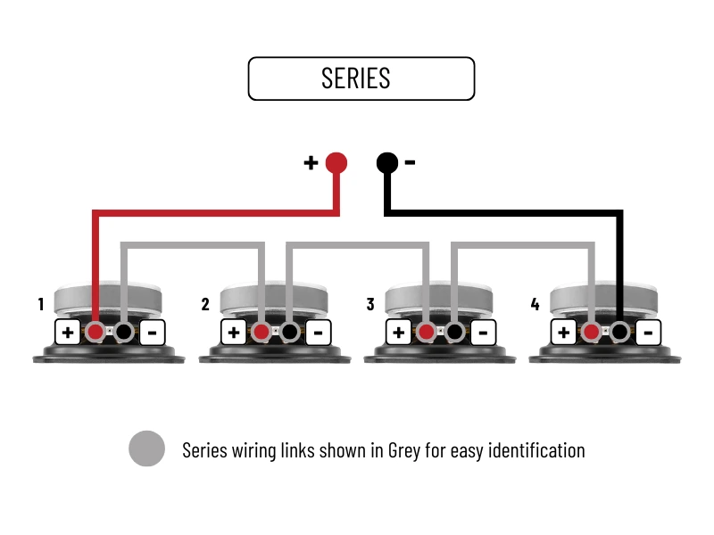
Series Wiring (see image)
- From the amplifier’s positive (+/red) output, you take a cable to the positive (+/red) terminal of Speaker 1.
- From the negative (-/black) terminal of Speaker 1, take a cable and connect it to the positive (+/red) of Speaker 2.
- Speaker 2 negative (-/black) links to Speaker 3 positive (+/red).
- Speaker 3 negative (-/black) links to Speaker 4 positive (+/red).
- From Speaker 4 negative (-/black), run your cable back to the amplifier's negative (-/black) terminal.
- We show all series link cables as Grey in the illustrations.
Series wiring certainly has its uses, but you must be careful with speaker numbers and your impedance calculations. The wiring is technically simpler than parallel, though you can easily get in a mess with either if you don't know what you are doing. If you do decide series is the best option, try to wire and test the system before installation to see if the sound is at a standard you will be happy with, as high impedance loads can significantly lower amplifier performance and dynamics.
Pros:
- Safe for amplifiers with lower power ratings.
- Easy to wire and calculate.
Cons:
- Higher impedance means less power to each speaker.
- The amplifier runs cold so loses dynamics which can lead to a thin or weak sound.
- Daisy-chain wiring means any wire breaks will stop all the speakers from working.
- Not ideal for high-volume setups.
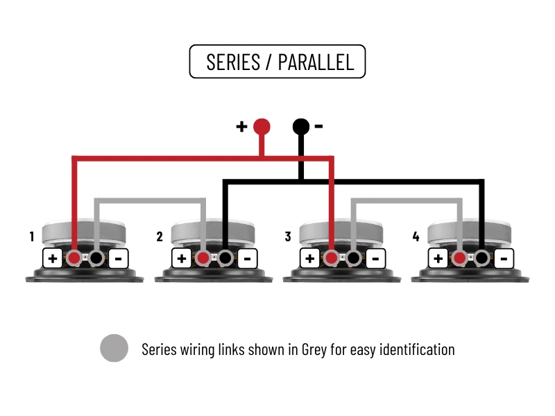
WIRING SPEAKERS IN SERIES/PARALLEL
Series/Parallel wiring combines the best of both worlds, allowing you to balance impedance and output. This method is great for large setups with four or more speakers. It’s actually the safest electrical way to connect 3 or 4 speakers to an amplifier channel directly. Surprisingly (or not) it's often avoided due to its perceived complexity, yet it can solve multi-speaker issues in so many situations.
Understand the Concept
Speakers are divided into pairs and wired to each in series. Those pairs are then connected to the amplifier in parallel. So for our 4 speaker example, lets say that they are all 8 ohm speakers. You will link two together from the negative (-/black) of one to the positive (+/red) of the other. You then do the same for the second pair. These are series links, so for each linked pair you add the impedance together, so 8+8 here to give you 16 ohms. You have two pairs, so it's two separate sets of 16 ohms.
You then wire both the unconnected positives (+/red) to the positive (+/red) of the amplifier, and both empty negative (-/black) terminals back to the negative (-/black) of the amplifier. This is a parallel connection. So in doing this, your two 16 ohm sets are now in parallel, so you divide the impedance by the number of sets, so 16/2 here, which gives you a total of 8 ohms in series/parallel.
Now you can see why it's handy!
Connect the Wires
Series/Parallel Wiring (see image)
- From the amplifier’s positive (+/red) output, you take a cable to the positive (+/red) terminal of Speaker 1 and Speaker 3. These can be both direct from the amplifier as shown, or if preferred you can go from the amplifier positive (+/red) to Speaker 1 positive (+/red), then loop to Speaker 2 positive (+/red). You are making an identical connection either way.
- From the amplifier’s negative (-/black) output, you take a cable to the negative (-/black) terminal of Speaker 2 and Speaker 4. These can be both direct from the amplifier as shown, or you can go from the amplifier negative (-/black) to Speaker 2 negative (-/black), then loop to Speaker 4 negative (-/black). You are making an identical connection either way.
- Speaker 1 negative (-/black) links to Speaker 2 positive (+/red).
- Speaker 3 negative (-/black) links to Speaker 4 positive (+/red).
- We show all series link cables as Grey in the illustrations.
The scariest of all the wirings....It can strike terror into the heart of the average electrician just being mentioned, but it really isn't that complicated. If you understand how the impedance is affected and can do the maths, you will find that for connecting larger numbers of low impedance speakers, it really is your friend.
Pros:
- Balances impedance and power distribution.
- Ideal for complex, multi-speaker setups.
- Keeps the amplifier at a good operational loading.
Cons:
- Slightly more complex wiring process.
- Requires careful impedance calculation, especially if speakers are not all the same impedance.
SPEAKER CONNECTION TYPES
A standard loudspeaker has two terminals: positive (+) and negative (−). These are typically marked or colour-coded (red for positive, black for negative). This is the same for speaker drivers and for enclosed speakers (eg, wall speakers or floor-standing speakers). These markings will be matched at the amplifier's speaker terminals, and will usually be labelled clearly to identify the left and right channels required for stereo.
Though there are many types of speaker connectors, it’s important to understand they are all doing exactly the same task, delivering the positive and negative sides of the signal whilst maintaining the correct polarity.
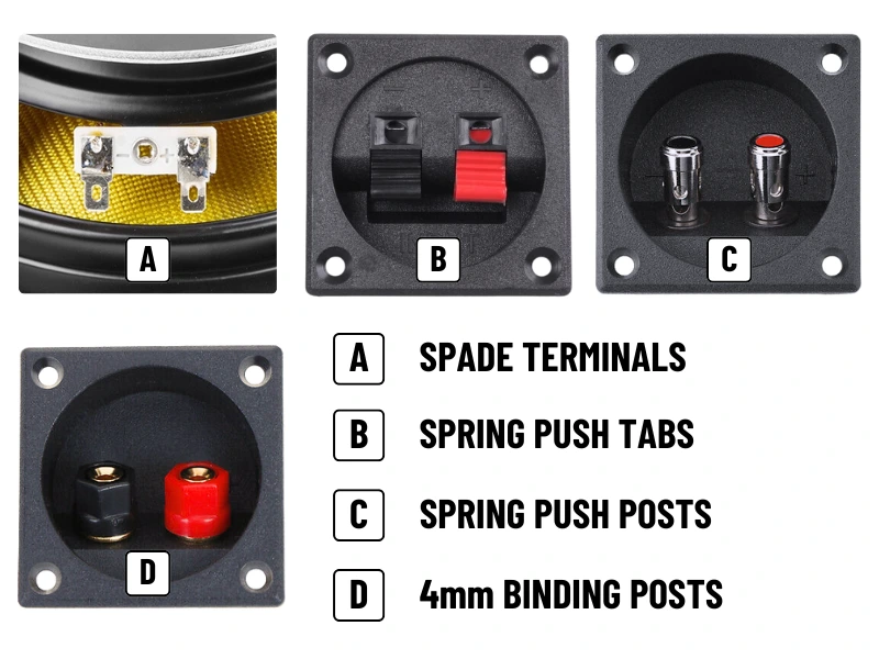
Spade Terminals - (Pic A)
A speaker driver (woofer, tweeter etc) will for the most part have spade connections. The cable can be connected to these either with solder, or the appropriately sized spade crimp connector. The size of the spades varies between speaker size and manufacturer, so crimps would need to be purchased to suit. The positive and negative sides will usually be identified with a stamped marking.
Spring Push Tab - (Pic B)
At the more budget end of things, the classic spring-loaded push terminals, which are a set of black and red toggles which you push to reveal the black plastic cable opening. The spring pressure clamps down on the inserted cable to make the connection to its metal insert. They work ok, and are a secure enough connection. The downside is that they can only accept fairly thin cable, and the spring mechanism is prone to failure over time.
Spring Push Post - (Pic C)
These are a newer design that has been showing up on midrange equipment. It’s a bit of a naughty design really as to the uninformed it closely resembles the more professional 4mm binding post with its large posts with colour-coded top inserts. They are however a simple spring push design that only accepts bare wire. The inserts are not removable and they do not accept banana plugs, despite some retailers stating so. They do however accept thicker cable than the push tab design.
4mm Binding Post - (Pic D)
Once only found on higher quality Hi-Fi but now becoming the standard for all audio equipment, the binding post is a far more solid design. The individual posts are metal with a coloured plastic outer shell. The shell is threaded and can act as a clamp, with bare wire cable being fed through a hole in the metal post, or wrapped around it. This also allows the clamping of large forked or pin-style connectors.
The post is also hollow-centred to accept the industry standard 4mm connector, affectionately known as the banana plug, which is a favourite of Hi-Fi enthusiasts due to its larger metal-to-metal contact area and ability to accept heavy gauge cables.
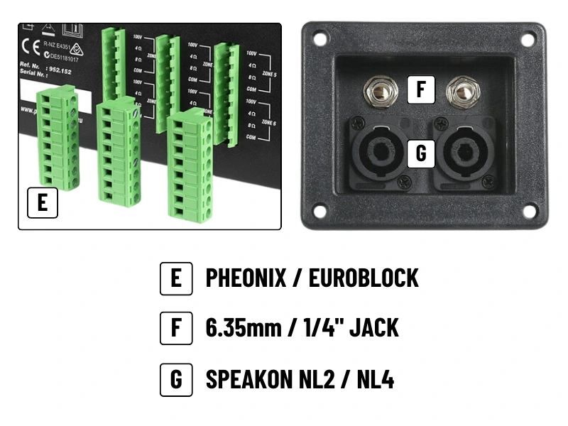
Pheonix/Euroblock - (Pic E)
Most commonly found on 100V line speakers and amplifiers, these do show up on non-commercial equipment too. The Phoenix Contact company invented them so they were always known as Phoenix connectors, though the many copies over the years fall under the ‘Euroblock’ moniker. They come in several colours and are usually a right-angled plug and socket design with screw-clamp cable terminations.
6.35mm Jack Sockets - (Pic F)
More worldly known by its imperial measurement of a quarter inch (¼”), the jack plug is an industry standard for PA speaker connections, wired headphones, and for musical instrument signal transfer. These chunky metal plugs have lots of surface area and can accept heavy-duty 2-core speaker cable. The positive and negative cables connect via solder tabs inside the same plug, saving space and simplifying wiring on amps and speakers.
Speakon Sockets - (Pic G)
The heavy-duty option found on professional PA speakers and amplifiers. These durable plugs and sockets feature a twist-to-lock design and come in either 2-pole (NL2) or 4-pole (NL4) options to allow for heavy gauge cable and easy series/parallel wiring to speaker stacks or line-array systems.
Read More...
5 SPEAKER WIRING - POLARITY/CABLE TYPE/IMPEDANCE
Let's have a quick look at the other important factors to consider when wiring loudspeakers. We also cover these in far more detail in some of our other guides, so be sure to take a look if you want to learn more.
Speaker Polarity
Polarity. The reason why the terminals are coloured or marked as positive and negative. Without getting mega techy, an audio signal is an electrical waveform, which swings positive and negative from a zero position. This positive and negative swing, or push and pull if preferred, is how a speaker works, by moving forward (positive) and backward (negative) in response to the incoming signal, and recreating that waveform by disturbing the air pressure in front of it.
Human hearing works by our eardrum interpreting those positive and negative changes in air pressure and our brain converting them back into a waveform, which it then decodes as music (or any noise).
The reason this is important is that the connection between the amplifier and speakers requires the user to ensure those positive and negative signal sides are kept correct. A simple flipped connection at one end of the speaker cable will see the speaker moving backwards when it should be going forward, which sounds truly awful when two or more speakers are being driven and one is wired incorrectly.
This is often called being ‘out of phase’, even by some professionals, which is incorrect. Phase is a different thing completely as it involves a timing variation (we will cover that in a different article), whereas polarity, or reversed polarity, is purely the swapping of the positive and negative signal halves. You may not even notice incorrect polarity if you are only driving a single speaker, and it usually only becomes audible when two or more speakers are working, with one being wired incorrectly.
It won't do any damage to the amp or speaker, so it isn't a total disaster, just that it won't sound very nice!
Speaker Cable
Speaker cable is marked for easy identification of polarity (speaker cable is usually a pair of wires bonded together by their plastic covering). This may be something obvious like red and black outer sheathing to each core, or, if the cables are the same colour, the negative will be marked with some sort of printed identifier mark or a physically raised ridge along its length.
Electrically it doesn't matter, as the cable itself has no polarity, so you can use whatever is suitable to the task, but just ensure you connect positive to positive and negative to negative between equipment and you will be just fine.
If your connections are Speakon or 6.35mm Jack this is no different, despite them both being a single plug and socket design as opposed to positive and negative terminals. If you are making your own cables, the screw clamps in a Speakon plug are clearly marked, and for a standard mono Jack, the negative will always be the body or ‘sleeve’, with a positive connection to the tip of the plug.
For installers using cable off the roll, and especially for longer distances, you must ensure the cable is electrically up to the task by looking at current ratings (we have guides covering cable types and lengths), and the cable must be physically durable too if it's being pulled through walls and ceilings. This is what's called a double-insulated cable, which takes the standard two cable cores and encases them inside a single outer covering to provide extra protection.
For premade PA speaker cables such as those terminated with Speakon or Jack, take note of the cables core sizing (eg, 2x 1.5mm or 2x 2.5mm) as they are not all the same despite looking identical, and always go with the best quality you can to ensure the plugs and cable are the proper types and not cheap copies that won't last.
As a general rule, especially for low impedance and high output systems such as PA, you always want to use the shortest cables possible. The longer the cable, the more resistance, which causes heat buildup and volume loss, causing a serious drop in efficiency and system performance. As a general rule, anything over 10m you should be upping the copper core content to compensate (so say 2x 1.5mm for up to 10m, then it should 2x 2.5mm if it’s 15m to 20m).
Just keep this in mind. We will take a look into cable lengths and calculations for both low impedance and 100V line systems in their own more in-depth guides.
Speaker Impedance
Every speaker has an impedance rating, stated in Ohms Ω. Think of it as a measurement of how hard that speaker is for the amplifier to drive. The standard for Hi-Fi is generally 8Ω, while passive PA speakers will be 8Ω or 4Ω. The lower that number, the more effort the amp has to put in, and vice versa. Amplifiers will have a stated operating range (often 4Ω to 8Ω), though some will allow up to 16Ω, or down as low as 2Ω, but these are rare and usually expensive.
Impedance is your guide of electrical compatibility between speakers and amplifiers. It gives you a set of rules to work within which are intended to ensure safe operation and the best performance.
Impedance mismatches or overloads are one of the fastest ways to destroy a perfectly good amplifier. It's important to get right when using just a pair of speakers, but any more than a pair and it's completely essential for you to understand and calculate for impedance loading, to avoid disaster.
You can read more about impedance in the guide - Understanding Parallel and Series Speaker Wiring
6 WIRING TIPS & PITFALLS TO AVOID
- Mismatched Impedances:
- Overloading the Amp:
As previously discussed, wiring too many speakers in parallel can drop the impedance dangerously low, risking severe amp damage. Most amplifiers have a lower impedance limit of 4 Ohms, which is already making the amp work hard. Go below that and you will cause severe damage, unless the amp specifically states that it's capable of doing so.
- Underpowering Speakers:
- Use Quality Cable:
- Measure Twice, Cut Once:
- Check Connections:
- Double-Check Polarity:
- Test Before Finalising:
- Plan Ahead:
Mixing speakers with different impedances can lead to uneven power distribution and distorted sound. If you can avoid it then do so. If you really must mix loadings you must do the required impedance calculations, and understand that the power distribution between speakers will be uneven.
High impedance setups may result in weak sound if the amp can’t deliver enough voltage. Series wired systems can quickly take impedance levels to a point where the amplifier will be delivering less than half of its potential.
As a general rule, use at least 2x 1.5mm² cable where possible. You can certainly get away with 0.75mm², but it's such a minimal cost difference to use 1.5mm² or larger and you get far superior resistive, thermal, and current handling properties from the extra copper content.
If you are doing an installation, especially a multi-room system, you will likely be running cables through walls or in ceilings. The last thing you want is for a cable to be fed through than not be long enough, so take measurements first and always add on a few metres extra just to cover yourself.
If terminating cables into connectors (soldered or screwed), you should always check your connections visually and with a multimeter before use. It's very easy to miss a solder joint, ground out a positive connection, or flip the polarity, especially when preparing multiple cables at once. It’s much better to find an issue at this point rather than trying to trace it later on.
Ensure positive connects to positive and negative to negative to avoid phase issues (which can make your speakers sound odd).
Either use a specialist cable continuity tester or play some audio to ensure everything is working correctly before tidying up your cables. Sometimes this may not be possible, but if you can do it you should. It's a whole lot easier to chase problems or silly mistakes before everything is finished.
For multi-speaker setups, follow one of the methods described earlier, but it can also be a good idea to sketch your own diagram with your specific equipment and speaker quantity as you may find it easier to follow.
7 FINAL THOUGHTS
Whether you go for parallel or series wiring depends on your specific needs and the equipment at hand. Parallel is the go-to for most modern systems where volume and efficiency are key, while series is a safe choice for protecting your amp in larger, distributed setups. If you are feeling extra saucy you can venture into series/parallel layouts, and they can be extremely useful for multi-speaker systems.
Understanding impedance loading and the different wiring configurations is an essential part of creating an audio system that sounds good and is reliable. We have covered enough here to give you a good starting point, but do always encourage further learning by taking a look at our other guides.