
How to Wire 100V Line Speakers
A 100V line audio system is a type of sound distribution setup used primarily in commercial environments, such as offices, schools, shopping centres, or outdoor venues, where multiple speakers need to be spread over large distances. Unlike low-impedance systems, a 100V system allows long cable runs without significant loss of power or audio quality, thanks to its high-voltage, low-current operation. This makes it perfect for installations requiring several speakers across wide areas.
In this article: We’ll explain everything you need to know about wiring a 100V line Speaker System, including…
The key advantage of a 100V system is its efficiency. It allows you to run thinner, cheaper cables over long distances and still maintain consistent sound levels. With a 100V system, you can also easily add or remove speakers without affecting the overall load on the amplifier, and all the speakers are connected in parallel for the simplest of wiring.
Focussing specifically on wiring here (our other guides cover equipment choice in detail), let’s take a look at some of the common wiring methods for single-zone and multi-zone audio systems.
Looking for 100V Speakers?

Basic 100V Single Zone Speaker Wiring
Wiring Connections
Starting with the most common single zone/area wiring that you might use in an office or a small restaurant with one main room, you can keep things really simple in terms of wiring.
Looking at the image below you will see the output terminals of a single zone amplifier, which are clearly labelled. As with many 100V line amplifiers they also offer options for low impedance, in this case, you have 4Ω, 8Ω, and 16Ω terminals, along with a 70V output which is for the American market. (It can be used in the UK, but you generally wouldn't).
For our purposes, the only ones you need are the 100V and the common COM, which are fed to your positive and negative speaker terminals. Remember that 100V line is mono, so you won't find a left and right set of outputs as you would find on a Hi-Fi or PA amplifier.
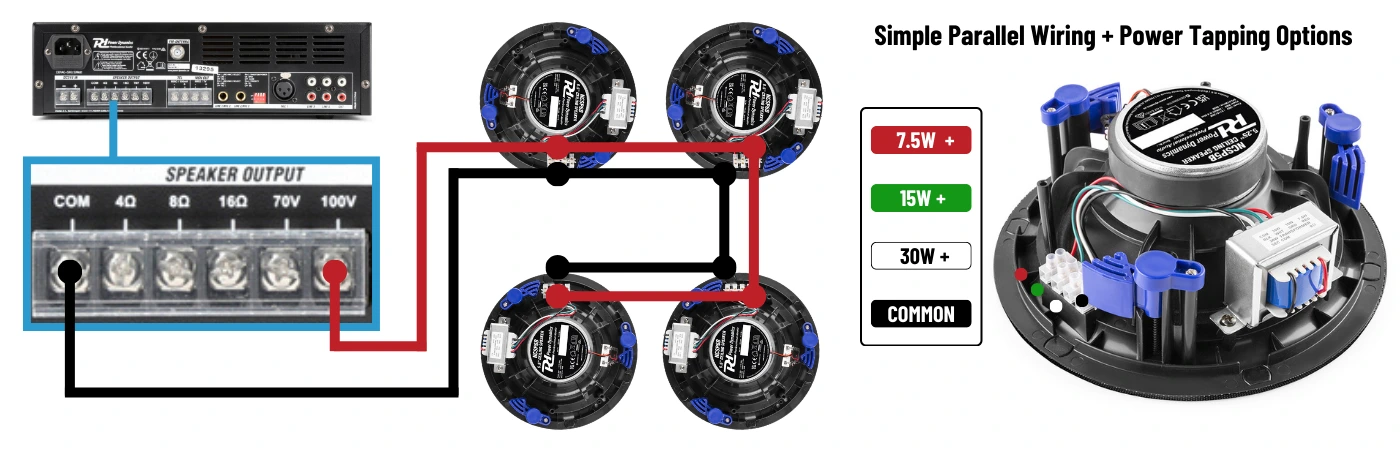
The example below shows a simple parallel wiring connection chain to four ceiling speakers. Using a 2-core speaker cable, you take a positive and negative from the amplifier to the terminals of the first speaker, then link from there to the next speaker and so on. This means you will have two positive and two negative cables to connect to all but the last speaker. Most 100V speakers have terminal block connections so this is not a problem, though electrical ‘chock blocks’ can also be used if it makes things easier.
Speaker Power Tapping
On the same diagram, using the Power Dynamics NCSP5B ceiling speakers as our example, you can see the transformer mounted on the back of the speaker which has 4 coloured wires going into its terminal block. This is where you will be connecting your speaker cable.
You have a common terminal for your negative (COM) connection, and for the 100V positive wire you can choose between 3 options of 7.5W (Red), 15W (Green), or 30W (White). These are your power tappings and will decide how much power that particular speaker can pull from the system. The tap ratings are always written on a label on top of the transformer on ceiling speakers, or on the rear panel of a wall speaker.
It’s important to understand that each speaker can be tapped as you wish, and this will not affect the next speaker. So with this 4-speaker install for example you could take the positive from the amplifier into the 7.5W terminal of the first speaker, loop it out to the next speaker and wire it into the 30W terminal, then have speakers 3 and 4 tapped at 15W each. The 100V signal is unaffected by the tapping it’s looped from.
In that scenario, you are pulling 7.5W, 30W, 15W, and 15W from the amplifier, so 67.5 watts total. Were that the case, a 100W amplifier would give you all the power needed. If however, you had tapped all four speakers at their 30W setting, you would need 120W total, requiring ideally an amplifier of around 150W. A power ‘buffer’ of between 20-50% is always desirable for any audio amplifier.
Multi-Zone Wiring from a Single-Zone Amplifier
System Uses
Common in retail and commercial installations, the use of a single-zone amplifier keeps things simple. The amplifier volume control affects all the speakers on the system regardless if they are located in different rooms or areas, as they are still all wired on the same cable chain.
This is the standard for most low-level background music and announcement requirements. It means the system can only be controlled from the main amplifier, which ensures a uniform volume level throughout. Music playback is limited to a single source, and every room or zone will have the same audio playing at the same volume.
You can modify this slightly with the addition of wall-mounted attenuators if you need to have independent volume control in one or more of the areas. Perhaps you have a meeting room or break area where the volume may need to be lowered or turned off. An attenuator is simply wired into the chain at the required point, with the same in/out method used to connect the speakers.
Wiring Connections
As with the wiring from section 1, the only connections you need on the amplifier are the 100V and the common COM, which are taken to your positive and negative speaker terminals.
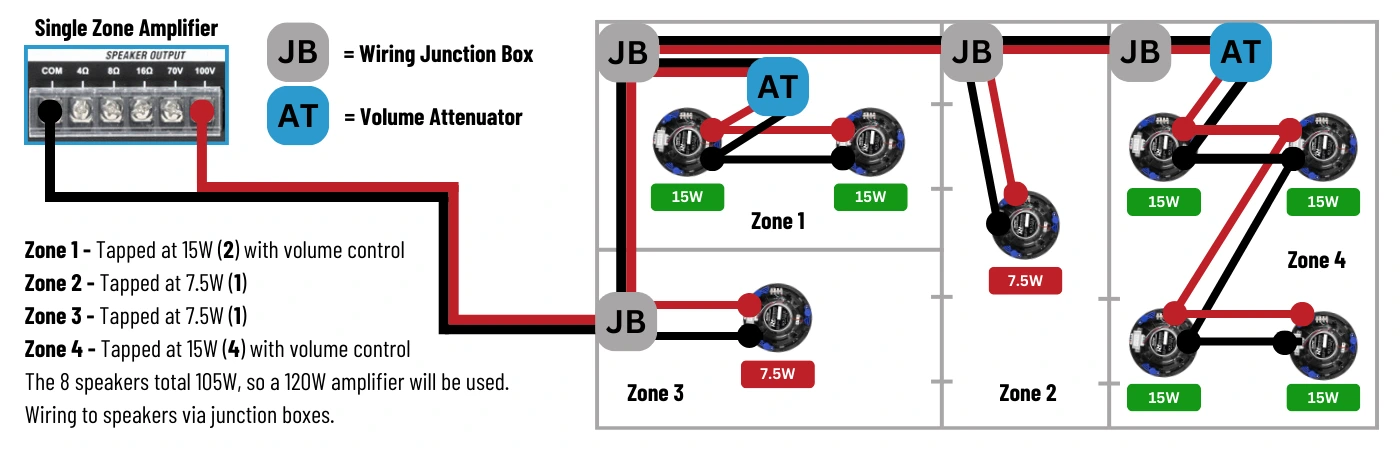
Our diagram below shows a 4-Zone audio system using a Single-Zone amplifier using a simple parallel wiring connection chain to Eight ceiling speakers. Using a 2-core speaker cable, you take a positive and negative feed from the amplifier to the terminals of the first speaker, then link from there to the next speaker and so on.
This time we have added volume attenuators into Zone 1 and Zone 4, and for a more professional wiring installation we are also using cable junction boxes to each zone. (you can read more about junction box wiring in section 4, and attenuators in section 5), but as you can see, both of these just interrupt the wiring, allowing it to continue the feed to the next junction while spurring off to each speaker.
What must be taken into account when using in-line attenuators in this way is that the amplifier volume is still used to set your system's master output level. The room attenuators can then lower that volume further, affecting only the speakers fed from them.
The speaker power tappings used in the diagram are just for example, but it’s worth noting that the difference in ‘loudness’ between the zones isn't as huge as the numbers may suggest. Without getting into a different subject, the audible difference between a 7.5W and 60W sound output is about 10dB, so the 4-speaker room with no attenuation applied will sound roughly twice as loud to human ears as the 1-speaker room. This gives the bigger zone a little legroom when needed, but nothing extreme.
Multi-Zone Wiring from a Multi-Zone Amplifier
Multi-Room Control
Using a multi-channel amplifier and a slightly different wiring method, we get what is arguably the most sensible option for a multi-room speaker system as it gives you total control of volume for each zone.
What else it does is allow you to wire separate cable runs from the amplifier to each zone, which is far more logical and straightforward in a larger install than having all the speakers in different rooms on one giant cable loop, and can often mean smaller gauge cable can be used.
Multi-zone 100V line amplifiers can usually be found with up to 6 output channels, and we have used one of these in the example below, though in this case only 4 zones are being used. As with the single-zone amp, you have a master volume control for the overall system maximum, but you also have volume controls on the amplifier for each of the 6 zones.
This allows you to set volume levels in each zone from one location and stops those zones from being altered locally. If you need in-room attenuation then they can be added as seen in section 2, but we have excluded them in the diagram below.
Wiring Connections
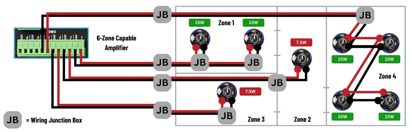
You will see in the diagram that the amplifier is sending separate 100V and COM wiring to each Zone. This is because the amplifier actually has 6 output transformers, each with its own connections. It’s this that allows you the control of volume level, muting, and sometimes tone control, to each Zone, while all outputs are sharing the same amplifier output power.
Again you will see that junction boxes are employed both for neatness and wiring convenience, with one for each speaker being ideal (Zones 1-3), or at least per zone (Zone 4) if preferred. We showed both here purely for example of what you can do, but per speaker is the most professional method.
For simplicity, we have used the same Eight-speaker layout with the same power tappings as used in section 2, which require a total of 105W of power. Similarly to that example, you could use a 120W amplifier, though, with two of the amps output zones unused, it would make more sense to go for a higher power amplifier which then gives you the freedom to utilise those additional zones at a later date if needed. This would also give you the capability to use higher output tappings on the speakers you have, or to add in additional speakers.
Wiring this way allows for easy addition of speakers to zones, and removal of zones completely if needed, without requiring a full system rewire. Many installers get it confused, but wiring this way is still all a parallel connection as the positives are all joined at the amplifier, just internally rather than all under the same clamp.
100V Line Junction Box Wiring
As you will have already seen in the previous wiring diagrams, we encourage the use of electrical junction boxes for 100V speaker cable runs. They provide many benefits on top of just keeping everything neat, tidy, and protected.
The simple ‘daisy-chain’ wiring example shown back in section 1 requires the cable from the amplifier to be fed into terminals on the back of a speaker along with a second cable for the loop out to the next speaker. So you have two bits of cable pushed into one, often small, terminal, which immediately creates a weak point in the line as all it takes is poor clamping or a snag on the cable during speaker installation and you can get intermittent issues or total line failure.
The use of junction boxes allows for a theoretically unbroken line from the amplifier to the last speaker. The speaker is wired into this junction as a spur, in an identical way to how a lighting fixture or mains socket would be done. If the speaker were to fail (open circuit transformer for example), it would not affect the rest of the run.
When doing an installation, the use of junctions allows you to run your cable completely to the last speaker and test the line without needing all the other speakers attached as they are no longer being used as cable connection points. This gives you great flexibility for last-minute speaker location changes and avoids having easily damaged speakers installed during the early stages of construction or refurbishment.
Also, it allows the use of heavier (2.5mm² onwards) speaker cables on the main run, which can then be dropped a gauge to say 1.5mm² or 0.75mm² from the junction spurs to the speakers, making wiring to the speaker's terminals much easier.
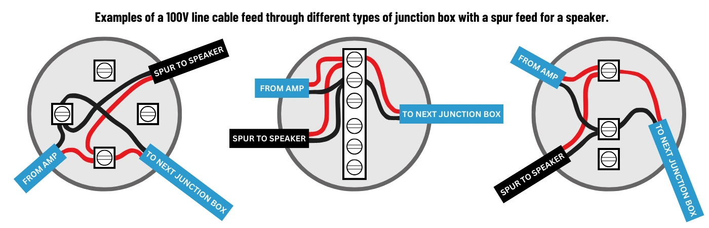
The image below gives 3 examples of 100V line speaker wiring with a spur off to a speaker. The drawing shows the same wiring, just with different designs of junction box depending on what you have or what's available to you. Following standard electrical wiring practices, the load (speaker) is connected to the incoming feed side of the wiring.
100V Line Volume Attenuators
A volume attenuator is a handy device in 100V line installation. Regardless of your amplifier and if it has built-in zonal volume controls, a wall-mounted attenuator gives you direct control for any room or area to lower the volume or turn it off completely, without affecting the rest of the system.
They are easy to wire into a system, just placed into the chain with the main speaker feed from the amplifier to its input terminals, and the output looped out to any speakers you want it to affect.
100V line attenuators work using a transformer or set of fixed resistors with set ratios of attenuation based on their maximum wattage rating. So in the same way that you would spec the required amplifier power by adding the wattage ratings of the speakers together, you spec an attenuator by adding the total wattage ratings of any speakers to be placed after it, and that gives you the rating of attenuator required. For example, if you have 6 speakers in a room that are all tapped at 10W, you would use a 60W volume attenuator to give you a full sweep of volume level control. They come in a range of ratings from 10W to 200W to suit many situations.
The most important factor when installing a volume attenuator is to use the correct rating, as they work in a similar way to the speakers tapping transformer. So if you put in a 20W attenuator in front of a 50W speaker, it's only ever going to get 20W with the volume fully up, regardless of the amplifier's volume. This works the other way too, so a 50W attenuator with a 10W speaker will be useless as it will basically just function as an on/off switch due to the attenuation ratio. The total speaker wattage and attenuator rating must be as closely matched as possible to function as expected.
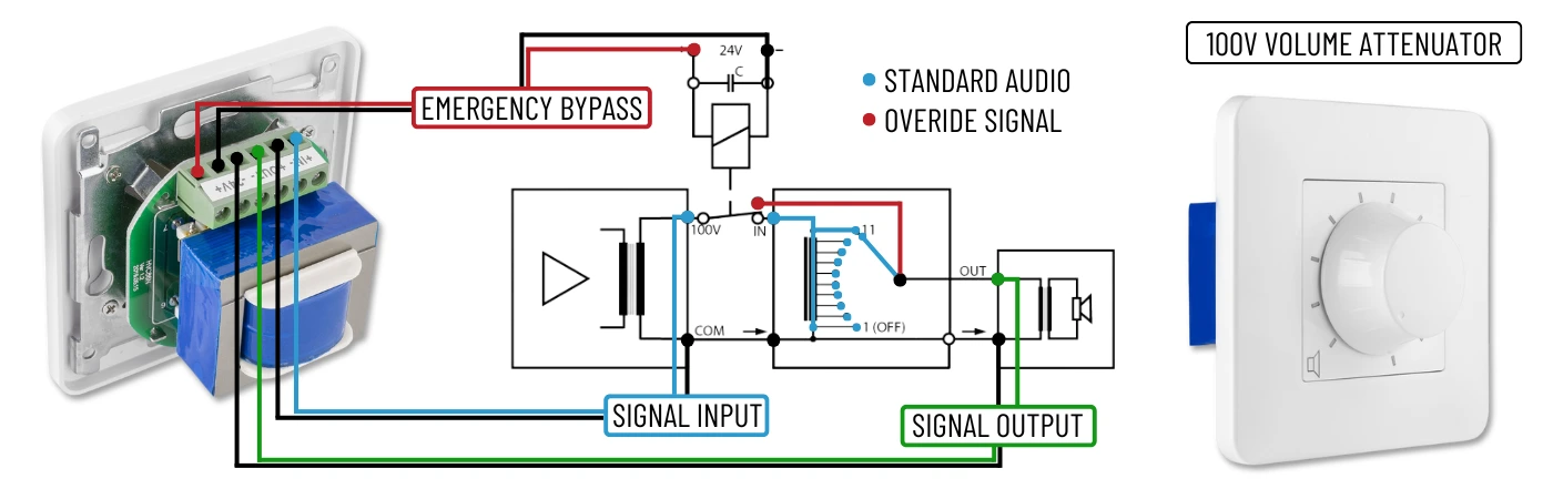
Unlike the volume knob on a Hi-Fi amp which is a smooth feeling action and affects the volume in tiny increments, a 100V volume is actually a series of notched positions, with each reducing the wattage tapping and lowering the dB output by a set amount. It’s a multi-position choke that limits the wattage available on the line.
So looking at the example in our circuit diagram you will see 11 positions, with 9 attenuation positions available. Position 11 links directly to the input signal (no attenuation, or full volume), and Position 1 is joined to the common signal to ground the line out (OFF). Remember that 0db is unity gain, so the dB reduction works on a minus scale, meaning position 10 on our unit will be -3dB, position 9 will be -6dB, and so on. On larger wattage units such as 100W, it's also common to find the last two positions feature 6dB drops, so taking that into account here would put Position 3 at -27dB, and Position 2 at -33dB (which is a whisper).
Many 100V line attenuators also include a remote-operated bypass relay which is energised by a 24V DC signal from the amplifier or paging microphone. The relay switches the input signal path and is wired directly to the output. This allows emergency announcements to be at full volume regardless of the attenuator setting, and will mute all other audio. This would be wired via two more terminals if used, and you can see this in the diagram below.
Read More...
100V Line - Good Installation Wiring Practices
As previously discussed, what you really should be looking to do with any 100V line wiring is take the amplifier output to a series of junction boxes. Running your speaker cable via junctions allows for a reliable transmission line from the amplifier to the final speaker, with each speaker along the way ideally getting its own spur from its own junction box instead of relying on an in-and-out connection being made at the rear of each speaker.
This also makes the inclusion of wall-mounted volume attenuators much simpler and neater, as again it can be fed via a spur, with its return line routed to the junction box of the first speaker in that particular zone, leaving the main speaker line unmolested.
With a pure daisy-chain install the system has so many potential failure points, especially when combining it with cheap cable which is easily snagged or damaged during the installation (being pulled through ceiling cavities for example). All it takes is one point in the chain to go down and everything wired after it will stop working, and it also leaves you no room for upgrades, layout alterations, or easy expansion.
Certainly, for a multi-zone or multi-room installation, you will want to be taking separate cable runs from the amplifier to each of those zones, and running junctions along those lines at your speaker positions.
For total peace of mind, some installers will use a 4-core speaker cable in the main run between junction points which gives you a backup cable pair connected, (two positives and two common feeds) When running cables through confined spaces over long distances it gives you both an error margin should a core go down or be damaged during a pull-through, and it doubles-up the current capacity while taking no extra effort to run.
Also worth mentioning here is unlike some audio or signal cable installs, a 100V line speaker system does not require any special resistors or impedance loads at the end of a cable run. You just stop wiring at the final speaker on that chain or zone.
100V Line - Wiring and Equipment at a Glance
Lets have a summary of the equipment types and terminology you may come across when dealing with 100V line audio:
Amplifiers Types
100V line amplifiers often come in several versions to suit different installation needs. Our range of PD amplifiers for example is available in various wattage ratings and with either single or multiple inputs and outputs.
They can include features such as Bluetooth, USB/SD media playback, microphone announcement priority (will lower or mute any music during an announcement), and things like volt-free or 24V DC emergency alarm triggering.
There are three types of 100V line amplifiers. Single-zone, multi-zone, or matrix. The differences are as follows:
-
Single-Zone: 1 Input Source and 1 Output Channel
These amplifiers will take the audio signal either from a built-in media player, Bluetooth connection, or connected source such as a CD player and send it to one set of output terminals. This can be wired as a daisy chain to multiple speakers. The system's volume is controlled by the amplifier and all speakers will playback the same audio.
-
Multi-Zone: 1 Input Source and 2 to 6 Output Channels
These come with a variety of output channels or zones to suit your installation. A small restaurant for example may have a bar area and dining area that can utilise the separate zones of an amplifier to allow easy volume control or muting to either or both areas. It simplifies the wiring and gives you zonal volume control from a single location. They are still a single input amplifier though, so the zones will all be playing the same audio.
-
Matrix: 4 to 6 Input Sources and 4 to 6 Output Channels
The kitchen sink of 100V amps. A matrix unit gives you the input functionality of an audio mixer and allows each of its input channels to be directed to any of its outputs at the same time. So for example, if you have 6 output zones, you could have a Bluetooth stream from Spotify playing in three of them, a CD in another, and FM/DAB radio in the other two. The zones can be swapped and muted with push button selection on the amplifier, and each zone volume can be controlled.
Amplifier Power
It’s common practice to design a system with at least 20% spare capacity, so if you have 80W of speakers, you should buy a 100W amplifier or larger. This allows for the amplifier to run more efficiently and also allows for later changes to individual power taps for areas that might need a bit extra volume.
Choose your speakers first to suit the location and audio requirements. Then simply add their wattage ratings together, add 20%, and that’s the output power of the amplifier you will need.
Remember that the power tappings on 100V speakers will allow you to tweak those numbers. For instance, you may like the design of a specific speaker that's got a 50W rating, but if you know it only needs half that power or less and will never be altered, you can wire to a lower tapping and spec a lower output amplifier.
Wiring Polarity
100V amplifiers are marked with COM (-) and 100V (+) on the output terminals and at the speaker's input connections. Unlike the red and black terminal identifiers used in PA and low-impedance audio, 100V relies on you to read the markings and use the correct terminals.
Most 100V line amplifiers will also have low-impedance output terminals (4Ω, 8Ω etc) and it is imperative that these are not used when wiring to 100V speakers. You must also never mix 100V and low-impedance speakers. The two systems are not compatible and you will severely damage the amplifier.
When wiring to 100V wall speakers, you often just have positive and negative inputs and sometimes an extra set for easier daisy-chain output wiring, so it’s fairly difficult to get it wrong. The power tappings are set by a switch or dial control.
For 100V ceiling speaker wiring, you will often have a 4 or 5-way terminal block. The negative cable will always go to the COM or negative connection, while your positive cable will go to whichever power tapping you have decided to utilise. The tapping ratings will either be written at the terminals or will be written on a label on the transformer.
You must maintain this polarity throughout your speaker circuit. The speaker cable you buy will either have coloured cores for easy identification, or a single colour sheath twin cable will feature a textured ridge to its coating on one core, which is generally used as the negative.
Volume Attenuators
Wall-mounted volume attenuation gives the convenience of lowering or muting a zone or a specific set of speakers on the system without needing to have access to the amplifier.
Most people like the ability to adjust the level of sound in their direct work environment, especially with background music which can become intrusive. Allowing for localised control makes it easy to set a comfortable volume, or mute the music easily in break areas or meeting rooms when needed without it affecting the entire system.
Speaker Cable
For quick reference here you just need to know that 100V line can operate over hundreds of metres using relatively low-gauge cable. For example, even using low-cost 2x 0.75² cable, on a system with a max speaker load of 120W, you can run 200m without issue.
It's all about ratio and capability, with higher wattage and longer distance requiring thicker cable to be used to combat signal loss and some other issues. As a general rule we encourage the use of 1.5mm² as a minimum on anything but a single room system, though you can calculate the cable gauge required using online calculators, or our comparison tables which are in our guide - 100V Line Speaker Cable Lengths and Losses
Final Thoughts
As with all electrical installation work, the pre-planning is one of the most important parts. Single or multiple rooms, the ceiling heights and types (if it has any!), the type of sound required, and of course, your budget, all dictate the equipment choices.
The methods for wiring generally stay the same though regardless, so our examples serve as a good basis for most systems, and give you an idea of how multiple speakers and zones can be wired in the most efficient and logical way.
Obviously, you can get more involved on larger systems, and we have several other guides which go much further in-depth on subjects such as parallel and series wiring techniques, and the technical differences of low impedance and high voltage audio systems.
The diagrams and explanations provided here have been kept as user-friendly as possible, so do err on the more simplistic side of things, though for most installations that is all you will need. Our expert team is always available too, and they are happy to guide you through equipment choices and system suitability.