
Understanding Parallel and Series Speaker Wiring
If you've ever dabbled in audio setups and installation, you’ve probably come across the terms series and parallel wiring. These aren’t just random jargon meant to make your life harder – they’re fundamental ways to wire speakers that affect your sound system's performance and longevity.
In this article: We’ll explain everything you need to know about wiring speakers, including…
Getting speaker wiring wrong will at the very least leave you with terrible sound, but more often, it will result in the fast destruction of the amplifier from overheating. Let's look at the reasons and differences between parallel and series wiring methods while covering a few other handy bits of related info you need to know.
What’s the difference between Parallel and Series wiring?
Parallel Wiring
By far the most commonly used method, you will generally be using parallel wiring for Hi-Fi and passive PA systems. It is reliable, logical, and if impedances are kept within the amps accepted range, will provide the best sound quality.
As long as the total impedance load of the linked speakers stays within the amp's capabilities, this method provides efficient power distribution and low distortion while increasing the volume level available. Get it wrong though and you will cook an amplifier quickly!
Each connected speaker can have its positive and negative connections fed directly from the amplifier's output terminals, or if preferred, a cable pair can be taken from the amplifier to the first speaker and then linked along to the following speakers.
Series Wiring
Series Wiring tends to be found in larger installations when an amplifier is feeding limited-frequency speakers, such as subwoofers or midrange banks in a club or auditorium, or in electric or bass guitar cabinets. The method is simple to wire and will reduce the loading on the amplifier due to the higher impedance/resistance.
Series wiring forces the power to flow through each speaker one after the other which raises the resistance. The reduction in loading to the amplifier from a higher impedance can cause it to run cold (barely working) which will squash its dynamic response, leading to a weak or ‘thin’ sound, especially in larger chains.
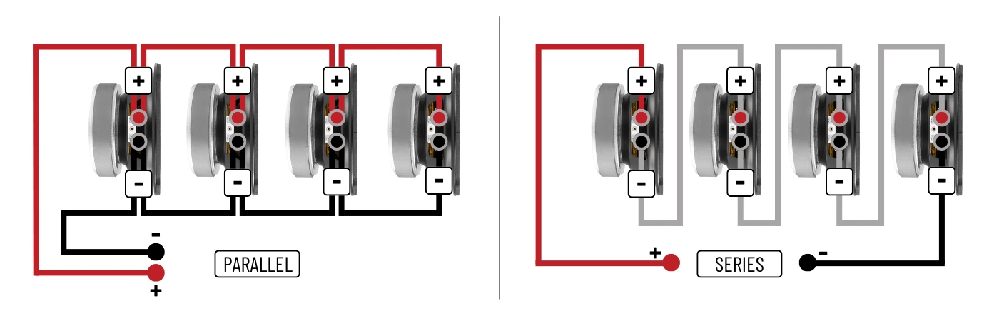
The wiring is basically a chain or loop, with a singular cable from the amps positive terminal that goes in and out of all the speakers, finishing back at the amps negative terminal.
The image below shows examples of the connection flow to four speakers. We show it to speaker drivers here, but wiring to speaker enclosures is no different.
Understanding the basics of Speaker wiring
Speaker Cable
You must think of speaker cable as power cable, which is exactly what it is. A surprising amount of people seem to think that ‘music’ is somehow coming from the amplifier and going down these magical wires…
They are power cables, with the singular task of transferring an audio (AC) signal made up of variable voltage and current, from its source at the amplifier to its destination at the voice coil of your loudspeakers, which are going to put up a fight before they do what you ask, which is called impedance.
To do this job efficiently and effectively the cables need to be capable of handling all those forces, from electrical to thermal, and this becomes even more so when adding extra speakers.
Speaker Circuit Wiring
For parallel circuits, the cable must be capable of handling the increased current being transferred, while in a series circuit, you want the cable to help lower the already high resistance, not add to it, which becomes worse over longer distances.
You will see the term ‘daisy chaining’ is used for cable connections that go from speaker to speaker with only one amplifier connection, and you will see it often. Technically though, it’s wrong for parallel, and correct only for series wiring, though it seems to get used for both depending on where you are sourcing information. A true daisy chain is a singular speaker line, coming from the amps positive output, feeding in and out of the speakers positive and negative terminals, and finishing at the amps negative terminal. As you will see from the diagrams, that is not the same as parallel at all.
It’s also worth noting that when all connected speakers are the same impedance rating, the amplifier power is shared equally between them, regardless of the wiring method used. This changes when impedances are mixed, and would require ohms law calculations (available online) to be performed to provide you with the correct power allocation. For the examples given in this article, we have gone with speakers of the same impedance for simplicity.
What is Speaker Impedance?
Before diving into speaker wiring configurations, you really need to know at least a little about impedance (measured in ohms, symbolised by Ω). It is a critical factor when dealing with passive speakers and audio amplifiers, and will often decide for you which equipment and wiring methods are suitable.
Impedance is quite an in-depth subject though, and we aren't going to go full rabbit hole on it here, so we will just cover the basics:
Impedance is the measurable electrical resistance of a speaker to the voltage and current flowing to it from the amplifier. With an AC signal (audio is AC), and a speaker driver being a variable frequency device with a mix of resistance and inductance from its moving components, a fixed resistance figure isn't applicable, instead requiring an impedance rating (resistance and reactance) to be applied.
The impedance of a speaker is variable depending on the frequency it's responding to, (an 8Ω speaker for example can swing down to 6Ω or as high as 70Ω) so for simplicity, a speaker is given a ‘nominal’ rating that is within a tolerance of its idle position, which for most consumer speakers will be 4Ω, 6Ω, 8Ω, or 16Ω.
Think of speaker impedance as a restriction to power (current), so a lower impedance loading (2Ω, 4Ω) requires more current to flow from the amplifier, and a higher impedance (8Ω, 16Ω) has the opposite effect. Both of these significantly affect the amplifier behaviour, so an amp will have a stated speaker impedance connection range that should never be ignored, especially its minimum level (usually 4Ω).
Low Impedance = More Current Flow = Larger Amp Loading = More Power Output
High Impedance = Less Current Flow = Smaller Amp Loading = Less Power Output
But more power sounds great I hear you say! Well, yes and no.
An amplifier has electrical and physical limitations which are dictated by its components and circuit design. The power transistors can only deal with so much current before they start to fail. They also get extremely hot doing so, which heats up the amps casing, causing other components to fail too. Excess current equals excess heat, which is the amp killer.
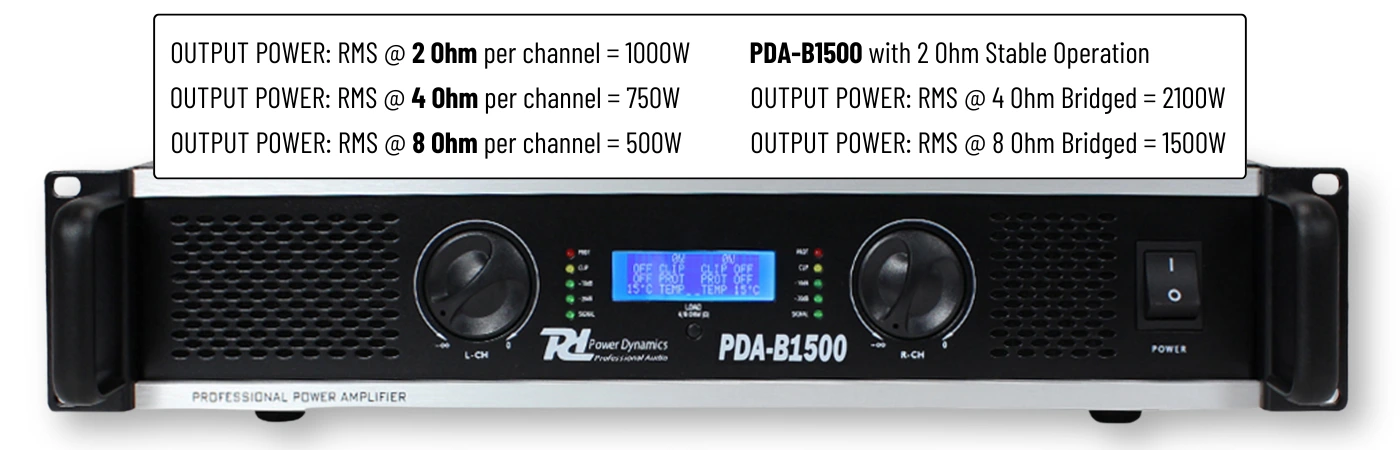
Power amplifiers, especially those designed for PA use, will often list their output impedance ranges along with how using each will affect the available output power. It can be quite surprising to see just how large the differences can be, and gives a great visual of the importance of choosing the correct speakers and wiring method to optimise performance and operational longevity.
The way an audio amplifier works requires it to have an electrical load to push against (a speaker). Think of it as a tug-of-war, with both parties needing to be of equal ‘size’ for balance. If either is larger or smaller, the effort becomes significantly one-sided, and the longer the rope (speaker cable), the worse it gets. Amplifiers are designed to work efficiently within a specific stated output impedance range, and wiring multiple speakers incorrectly can push the impedance too high (resulting in weak sound) or too low (overheating and damaging your amp).
It was partly for these issues that the 100V line system was designed and implemented for large commercial audio installations, as it removes speaker impedance completely, and allows huge cable lengths at extremely low levels of resistance, but that’s a discussion for a different article.
The image below shows the range of output impedances available on a PA amplifier, and how these drastically affect the power output available. I picked this particular power amp as an example because uniquely it includes a 2 Ohm output, which is seen on very few amplifiers due to the massive heat the amp will generate operating at such a low impedance/high current. Always remember that power comes at a price!
How does Parallel and Series wiring affect impedance?
Parallel Wiring
When you wire speakers in parallel, the total impedance decreases. Providing the speakers have the same impedance rating, you can simply divide the impedance figure by the number of speakers. Here are some examples: (also see IMAGE A below)
Two 8Ω speakers in parallel (8 ÷ 2) = 4Ω Load - Fine for most amplifiers
Two 16Ω speakers in parallel (16 ÷ 2) = 8Ω Load - Fine for most amplifiers
Four 8Ω speakers in parallel (8 ÷ 4) = 2Ω Load - Too low for most amplifiers
Four 16Ω speakers in parallel (16 ÷ 4) = 8Ω Load - Fine for most amplifiers
Why It Matters
Decreasing impedance increases power and volume, but might overload your amplifier as it increases the current. Check the amp’s specs – if it supports a minimum of 4Ω, wiring four 8Ω speakers in parallel for example would drop the impedance to 2Ω, which will cause severe overheating. Some amplifiers will even sense the load is too low and not even power on. This is simple enough to avoid though by doing the maths first and buying the correct impedance speakers, and the benefits of a parallel connection are well worth it. The parallel method also provides a level of redundancy in that the failure of a speaker will not stop the others from operating.
Series Wiring
When you wire speakers in series, the total impedance increases. Providing the speakers have the same impedance rating, you can simply add the impedance figures together. Here are some examples: (also see IMAGE B below)
Two 8Ω speakers in series (8 + 8) = 16Ω Load - Ok for most amplifiers
Two 4Ω speakers in series (4 + 4) = 8Ω Load - Fine for most amplifiers
Four 4Ω speakers in series (4 + 4 + 4 + 4) = 16Ω Load - Ok for some amplifiers
Four 8Ω speakers in series (8 + 8 + 8 + 8) = 32Ω Load - Too high for most amplifiers
Why It Matters
Higher impedance reduces the power delivered to the speakers by reducing the current from the amplifier, leading to lower output volume. While certainly ‘safer’ electrically for your amp than an impedance which is too low, it’s not ideal for sound performance. The reduction in power will lower the overall capability of the system, but also the lack of current in the amplification process will affect the signal's dynamic range, often leading to a thin or dull-sounding output. The looped wiring also means that if one speaker or cable fails, the entire system will go off. It does, however, allow amplifiers to run very cool which can be beneficial in specific situations.

Series/Parallel - The best of both?
Avoided by most installers due to the required maths scaring them off the idea. You can perform a mixture of series and parallel wiring methods as part of the same run, which can be handy for getting around unusable impedance figures caused by grouping speakers. It usually consists of wiring groups of speakers in series, and then each group is connected in parallel back to the amplifier.
As previously discussed, in series, you add the impedance values of each speaker, and for parallel, you divide the total impedance by the number of speakers. So, for series/parallel, the total impedance load is calculated by taking the total of each group in series, and then dividing that by the number of groups wired in parallel.
For example:
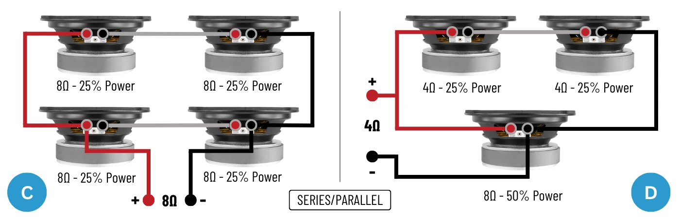
Four 8Ω speakers in a cabinet could be wired as two series pairs and a parallel group. If it helps make things clearer, once you add two speakers together in series (8Ω + 8Ω) and get 16Ω, think of this pair as one 16Ω speaker. You do this for both pairs, giving you two 16Ω speakers. When you then wire them in parallel to the output, you are dividing that overall impedance by the number of speakers (pairs), which in this case will be 16Ω divided by 2, giving you an 8Ω total impedance for all 4 speakers. (See IMAGE C below for a visual of this.)
Pair 1 - Two 8Ω speakers in series = (8Ω + 8Ω) = 16Ω
Pair 2 - Two 8Ω speakers in series = (8Ω + 8Ω) = 16Ω
2x 16Ω pairs wired in parallel = (16Ω ÷ 2) = 8Ω total
If you upped this to eight speakers with the same method:
Pair 1 - Two 8Ω speakers in series = (8Ω + 8Ω) = 16Ω
Pair 2 - Two 8Ω speakers in series = (8Ω + 8Ω) = 16Ω
Pair 3 - Two 8Ω speakers in series = (8Ω + 8Ω) = 16Ω
Pair 4 - Two 8Ω speakers in series = (8Ω = 8Ω) = 16Ω
Four 16Ω pairs wired in parallel = (16Ω ÷ 4) = 4Ω total
Series/Parallel is often favoured for 4x12” guitar cabinets, allowing several to be used from a single amplifier without causing issues. This was especially popular in the 70s and 80s before the mainstream use of large PA systems, when ‘walls’ of guitar amps and cabinets were used onstage.
A cabinet would have 4x12” speakers, often using 16Ω drivers wired in series/parallel to give a 16Ω total output. This could be connected to the amplifier directly (it would help the valve amp run cooler), or additional 4x12” cabs could be linked together in parallel, with four 4x12” cabs (a total of 16 speaker drivers) having a total load of just 4Ω.
Series/Parallel also allows you to use an odd number of speakers if required, and speakers of different impedance, while providing you a usable total impedance. For example, you may have a pair of 4Ω speakers and a single 8Ω speaker that you wish to connect together:
Two 4Ω speakers in series = (4Ω + 4Ω) = 8Ω
One 8Ω speaker wired in parallel = 8Ω
The two 8Ω loads are wired to the output in parallel = (8 ÷ 8) = 4Ω total
This configuration will produce a total load of 4Ω, as the series connection between the two 4Ω speakers creates an 8Ω load, which is then wired in parallel to the single 8Ω speaker, dividing the total impedance. It is worth noting that when wired in this fashion, the amplifier will send its power equally to what it sees as two equal, parallel loads, and the two 4Ω series speakers will then share their portion of that power.
Or in English, the 8Ω speaker will get 50% power, while the 4Ω speakers will share the other 50% equally, so each will get 25%. (See IMAGE D below for a visual of this.)
Though often ignored through fear, Series/Parallel offers great versatility and allows easy impedance mismatches to be overcome when connecting multiple speakers. You can of course also use speakers of different impedance ratings if you really need to, though this requires the use of specific Ohms Law calculations to work out the total loading, and how the speakers will share the power from the amplifier, so is a bit more complicated and is something we will look at in a different guide.
Read More...
Mono or Stereo Amplifier impedance loading
One thing that seems to never be mentioned or made clear in any how-to guide wiring guide is the question of mono or stereo, and how impedance works when wiring to an amplifier.
The biggest confusion with wiring for most people comes from the fact that amplifiers have a stated impedance range at their speaker terminals (eg, 4Ω to 8Ω), and diagrams for parallel and series wiring usually show speakers coming back to single positive and negative connection points.
So for example, you want four speakers on your Hi-Fi amplifier. You have two 8Ω speakers for the left side, wired in parallel to give you a 4Ω load, and the same for the right side. So following the same maths, that's two lots of 4Ω in parallel, which is 2Ω right? Which is too low for the amp? Well no…
What you need to understand is that an audio amplifier is a mono device. This means when you have a ‘stereo’ amplifier, what you actually have is a box with two mono amplifiers in it, and each output has its own, separate impedance range. So any audio amplifier with two output channels will usually just have a label stating its impedance range, but this is actually for each channel, they aren't linked. So if your amp states its range as 4Ω to 8Ω, that means each channel, or the left and right sides, has that range available, it's not a total. So for the example we gave above, you can connect a 4Ω load to one side, and a 4Ω load to the other, and the amps output channels will each see 4Ω (which is their minimum rating) and run just fine.
This is perhaps more obvious on a PA power amplifier, as these often label each side or channel as A and B, and each will have its own volume level. To use this in stereo, you would have your left speakers on one channel and right on the other channel and raise both volume controls. You would then use your mixer or source device as the master volume and to provide any tone adjustment. You can also use each channel in mono, with an independent audio source to each if required, and some allow the linking (bridging) of the channels for one big mono output.
On a stereo amplifier such as a Hi-Fi unit, however, things are a little different as they generally feature an integrated preamp. The two output channels are designed to provide the left and right sides of a stereo input signal in a controlled and balanced way, so you simply have the master volume to control the total level. The speaker outputs though are still independent, so impedance loading is still per side and not total.
You will find with audio amplifiers that certain terms are interchangeable, which can be confusing to the newcomer. Some manufacturers may simply refer to ‘left side’ and ‘right side’ outputs, while others will use ‘channels’. Usually, the latter is found on power amplifiers, where you have manual control of each output, while Hi-Fi amps will simply say left and right to keep things simple. They mean the same thing though, and all outputs are separate, which is why there are two sets of positive and negative connections.
FINAL THOUGHTS
As this is intended as a simple guide, we have only talked about speakers of equal impedance loadings, regardless of the wiring method used, and kept the number of speakers involved low. This helps keeps things nice and simple on the maths side of things which makes it easier to grasp, and realistically it's what you should always be going for to ensure consistent performance and predictable behaviour.
You can of course mix and match speaker impedances and types if required, you will simply need to do the required ohms law calculations to provide you with the impedance loading total. There are lots of online calculators for this, allowing you to just enter the speakers details and get your total figure. As previously mentioned, this mixed method will drastically effect the power and volume at each speaker, so its never recommended.
Hopefully, you now understand how the Parallel and Series methods work from a wiring perspective, and understand speaker impedance a little better, as the next step is to put these into practice, which you can do by following our guide - How to wire Speakers in Parallel or Series